Telvonic SYSTEMS
DAC, ACC and AEC: what's inside the cable
All three connect a switch, NIC or accelerator to its neighbour over copper twinax. The difference is what sits in the plugs, and that decides how you test them.
| Type | Electronics in the plugs | Reach | How it's tested |
|---|---|---|---|
| DAC (direct attach copper, passive) | None in the signal path, only a memory chip that identifies the cable | A few metres, shrinking as lane rate rises: about 2 m at 100G per lane | As a channel, with a VNA: S-parameters, crosstalk and channel figures |
| ACC (active copper) | Linear redrivers or equalisers | Somewhat longer than passive | Channel measurements plus powered checks |
| AEC (active electrical cable) | Retimers or DSPs that recover and regenerate the signal | Several metres, often up to 7 m | As an active link: bit error rate at line rate, diagnostics, power and management interface |
The plugs follow the module form factors: SFP for one lane each way, QSFP for four, QSFP-DD and OSFP for eight. A 400G QSFP-DD cable at 50G per lane and an 800G OSFP cable at 100G per lane both carry 16 differential pairs, eight in each direction, and every one of them has to be tested.
What to measure on a passive cable
A passive cable is a channel, so the measurements describe how it attenuates, reflects and couples signals across frequency. Each one tends to catch a particular manufacturing fault.
| Measurement | What it shows | Faults it typically catches |
|---|---|---|
| Insertion loss (Sdd21) | How much signal arrives, against a frequency mask | Wrong wire gauge or length, damaged twinax |
| Insertion loss deviation (ILD) | Ripple around a fitted loss curve, caused by reflections | Poor terminations at the paddle card |
| Return loss (Sdd11, Sdd22) or ERL | Energy reflected back to the transmitter | Impedance steps at solder joints and the plug |
| Differential impedance (TDR) | Impedance along the cable, and where a step sits | Crushed or kinked cable, bad joints, located by distance |
| Intra-pair skew and mode conversion (Scd21) | Timing mismatch between the two wires of a pair | Unequal conductor lengths, twinax damage |
| NEXT, FEXT and ICN | Coupling from neighbouring pairs, combined into one noise figure | Shield and drain termination faults, pair routing in the plug |
| COM | Margin of the whole channel against a reference receiver | Several small problems that each pass alone |
Channel Operating Margin (COM) is the figure recent IEEE 802.3 copper specifications use to judge a cable assembly as a whole. It combines loss, reflections and crosstalk with a reference transmitter and receiver, and cable assemblies in recent clauses typically need at least 3 dB. Effective Return Loss (ERL) plays the same role for reflections. PCIe cable specifications, including CopprLink for PCIe 5.0 and 6.0, and SAS specifications set their own loss, return loss and crosstalk limits and their own channel analysis. Take the limits for your product from the specification it claims, not from a generic table.
Frequency range and lane rate
Measure to at least the Nyquist frequency of the lane (half the symbol rate) and, in practice, to the upper limit your specification defines for each figure. For 100G-per-lane PAM4 (53.125 GBd) Nyquist is 26.56 GHz, so a 43.5 GHz analyzer or more is typical. For 200G per lane (106.25 GBd) Nyquist is 53.1 GHz, which needs 67 GHz. Our guide on how to choose a vector network analyzer has the full table by interface.
Fixtures, reference planes and de-embedding
A cable can't be connected straight to a VNA. Each end plugs into a test board with the host connector and cage, and traces carry the signals out to coaxial connectors. Those boards add loss, reflections and crosstalk of their own.
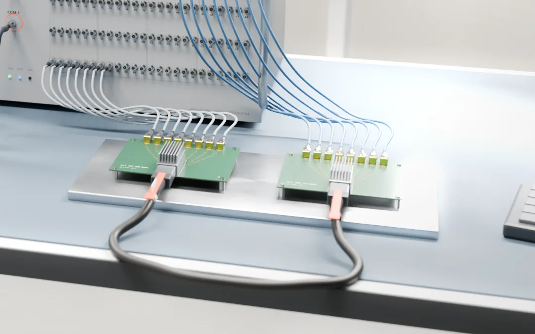
- Know where the limits apply. Specifications define the test points and whether a limit includes the test fixtures. Measure the way the specification does, or the numbers won't compare.
- De-embed the boards when the limits apply at the cable's connector. A 2x-thru standard (two fixture halves joined back to back) characterises each half so it can be removed. IEEE 370 describes the method and how to check that the fixture is good enough to remove.
- Watch the fixture itself. Host connectors and cages wear with every insertion. Count insertions per board, check a golden cable every shift, and replace the board before its rated mating cycles run out.
A production test station
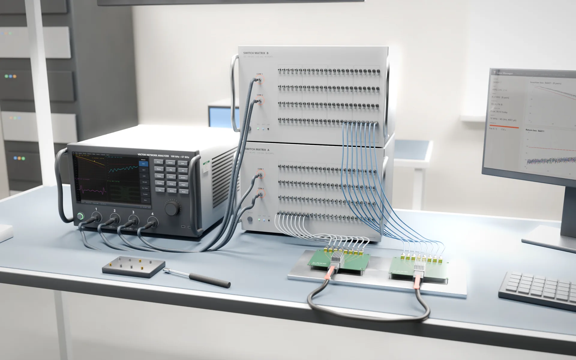
A QSFP-DD or OSFP cable with 16 pairs has 64 single-ended conductor ends. Testing it pair by pair on a 4-port analyzer means re-cabling dozens of times per part, which is slow and wears connectors. A production station instead connects every pair once:
- A 4-port VNA at the frequency your lane rate needs.
- A switch matrix that routes the analyzer to each pair in turn, and to the aggressor pairs for crosstalk. Two 96-port units reach 48 pairs.
- Test boards for each form factor, with known reference planes.
- Electronic calibration of every switch path, so a full calibration takes under an hour instead of a shift.
- Automation software that sweeps each pair, computes ILD, ICN, COM and ERL, applies the limits, saves Touchstone files and a report per serial number, and passes the result to the MES.
With a 10 MHz to 40 GHz sweep at 4,001 points, a thru measurement takes about 2 seconds per pair, so the thru set for a 16-pair cable takes around half a minute; crosstalk adds to that, depending on how many aggressors your specification asks for. Plug handling by the operator is often the larger share of the cycle, so design the fixture for quick, repeatable insertion.
What changes for AEC and other active cables
An AEC regenerates the signal in each plug, so the copper in the middle is no longer what the host sees. End-to-end S-parameters stop being the pass or fail criterion, and production test moves to the link:
- Power-up and management: current draw on each supply, temperature, firmware version, and the CMIS fields and alarms.
- Bit error rate at line rate on every lane in both directions, with PRBS patterns from a tester or the host, or in loopback where the cable supports it.
- Built-in diagnostics: many retimers report per-lane signal quality and error counters through CMIS diagnostics. Logging them per serial number shows weak lanes before they fail in the field.
- Electrical compliance of the host interface (output eye, jitter and noise, input stress tolerance) is usually measured in the lab during qualification and on samples, not on every cable.
The copper between the plugs still matters to the design, so many manufacturers keep a VNA measurement of the bare cable assembly before the active plugs are fitted, or on samples.
A test plan checklist
- The specification your cable claims, its test points and the limits for every figure
- Analyzer frequency to match the lane rate, with margin above Nyquist
- Port count: every pair connected once, through a switch matrix for multi-lane cables
- Test boards per form factor, 2x-thru de-embedding, and an insertion count per board
- Electronic calibration of every path, and a golden cable checked every shift
- Loss, ILD, return loss or ERL, impedance, skew and mode conversion, NEXT, FEXT and ICN, and COM where required
- Memory chip read, check and programming
- For active cables: power, diagnostics and bit error rate on every lane
- Results per serial number, Touchstone files kept, and the verdict passed to your MES
We build these stations as one system: analyzer, switch matrix, fixtures, calibration and software. See the cable test system, or send us your cable type and volume for a proposal.