 Telvonic SYSTEMS
High-speed cable & interconnect test. VNAs to 110 GHz.
A complete cable test system (CTS): vector network analyzer, multiport switch matrix, fixtures and automation software. It measures every pair of a DAC, AEC or high-speed connector from one hook-up and writes a pass / fail report against your standard's limits.
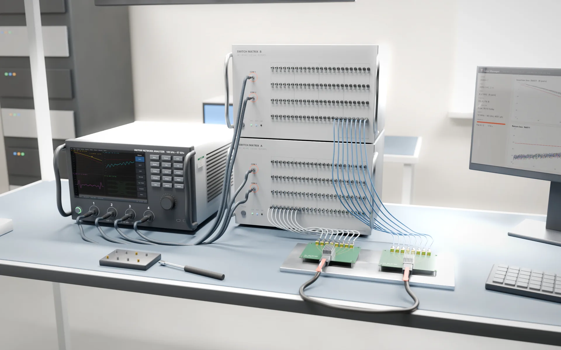
Two stacked switch-matrix units reach every pair of a 400G or 800G cable at once, so one hook-up covers thru and crosstalk measurements.
The system, in numbers.
What every cable goes through
- Mixed-mode S-parameters: insertion and return loss
- TDR impedance, delay and skew
- NEXT, FEXT, ICN and COM / ERL against the standard
Why cable test gets hard at 100G per lane.
Too many ports for one analyzer
A 400G or 800G cable carries 8 to 16 differential pairs, and crosstalk needs every pair connected at once. Re-cabling a 4-port analyzer by hand takes longer than the measurement and wears out connectors.
Margins in tenths of a dB
At 53 to 106 GBd PAM4, loss and reflection limits are tight. Switch, adapter and fixture paths have to be calibrated out or de-embedded, or good cables fail.
Every standard has its own maths
PCIe, IEEE 802.3, OIF CEI and SAS each define their own masks and computed figures such as ICN, COM and ERL. Working them out by hand from S-parameter files doesn't scale to production.
Five parts, one hook-up.
Delivered, calibrated and validated as one system. The switch matrix and software also work with an analyzer you already own.
Vector network analyzer
2- or 4-port at 26.5, 43.5 or 67 GHz, with time-domain and de-embedding options. Frequency extenders take it to 110 GHz.
Multiport switch matrix
DC to 40 GHz, 64 or 96 ports per unit, two units stacked for 128 or 192. Every pair of the cable is connected once and measured in sequence.
Test fixtures
Paddle-card fixtures for QSFP, OSFP or your own connector, with a defined reference plane so the fixture can be removed from the result.
Automation software
Sweeps every pair, computes the protocol figures, applies the limits and saves a report and Touchstone files per serial number, with results passed to your MES through Line Manager.
Electronic calibration
An e-cal module calibrates every switch path in under an hour, instead of a day of manual SOLT connections.
Every figure the standard asks for.
One sweep per pair; the software derives the rest from the S-parameters. What each figure catches
- Single-ended and mixed-mode S-parameters
- Insertion and return loss
- ILD and IRL
- TDR / TDT impedance
- Propagation delay
- Intra- and inter-pair skew
- NEXT and FEXT
- Integrated crosstalk noise (ICN)
- Insertion loss to crosstalk ratio
- COM and ERL
- Mode conversion
- Pass / fail against the mask
Switch matrix.
The heart of the system: it turns a 4-port analyzer into a 192-port one.
- Frequency
- DC – 40 GHz
- Ports
- 64 or 96 per unit · 128 or 192 with two units
- Connectors
- 2.92 mm
- Isolation
- > 65 dB
- Insertion loss
- < 1.1 dB per switch
- VSWR
- < 1.95
- Switching time
- < 15 ms
- Switch life
- 5 million cycles
- Size · weight · power
- 440 × 330 × 283 mm · < 19 kg · < 135 W
- Works with
- The analyzers below, or a VNA you already own
From 8.5 GHz to 110 GHz.
Inside the cable test system or on their own, for R&D, incoming inspection and production. Bars show each range on a 0 – 110 GHz scale; dashed is the upgrade path. How to choose one
8.5 GHz VNA
RF & antenna- 100 kHz – 8.5 GHz
- 135 dB dynamic range
- 50 Ω, 75 Ω with adapters
- Up to 20,001 points
Multiport 8.5 GHz VNA
Multi-site- 100 kHz – 8.5 GHz (50 Ω) or 3 GHz (75 Ω)
- 135 dB dynamic range
- Up to 12 two-port parts in parallel
- 4-port e-cal with smart calibration
26.5 GHz VNA
PCIe · 25G- 10 MHz – 26.5 GHz
- Up to 135 dB dynamic range
- Trace noise from 3 mdB rms
- −55 to +10 dBm output
43.5 GHz VNA
100G / lane- 100 kHz – 43.5 GHz
- Up to 135 dB (125 dB at 43.5 GHz)
- Up to 100,001 points
- Upgrade to 67 GHz, extend to 110 GHz
67 GHz VNA
200G / lane- 100 kHz – 67 GHz
- Up to 135 dB (120 dB at 67 GHz)
- 12.1-inch touchscreen
- TDR and eye-diagram options
110 GHz extension
mmWave · research- Extends a 43.5 or 67 GHz analyzer
- For 400G-per-lane research and W-band
- Same software and calibration flow
Electronic calibration module
Calibration- 100 kHz – 8.5 GHz
- One connection replaces a full SOLT sequence
- Calibrates a 24-port analyzer in 8 connections
Tell us the part, the frequency and the port count.
We'll recommend an analyzer, calibration kit and fixtures, and show you a demo on a sample of your part.
Talk to an engineerQuestions engineers ask us
Can the switch matrix and software work with a VNA we already own?
Yes. The switch matrix and the automation software also drive network analyzers from other makers, so you can add multiport cable testing to an analyzer already on your bench. We confirm model and driver support in the proposal.
Which analyzer frequency do we need?
Measure to at least the Nyquist frequency of your fastest lane, with headroom above it for time-domain results. As a guide, 26.5 GHz covers PCIe 4.0 and 25G-class lanes, 43.5 GHz covers PCIe 5.0 / 6.0 and 100G-per-lane cables, and 200G-per-lane work needs 67 GHz or more. We check the range your standard specifies before we quote.
How long does one cable take?
About 2 seconds per differential pair for a 10 MHz – 40 GHz sweep at 4,000 points. A 400G cable with eight pairs needs roughly 16 seconds of thru measurements; crosstalk adds to that depending on how many aggressor pairs your standard asks for. Everything runs from one hook-up.
How are the fixture and switch paths calibrated?
An electronic calibration module calibrates every switch path in under an hour, and the software keeps the error terms for each path. The fixture is then removed by de-embedding to the reference plane, so the report describes the cable, not the fixture.
Testing 100G or 200G per lane? Let's size the system.
Send the cable type, lane count, standard and monthly volume. We'll reply with a configuration and budget.
